Preprints & Reprints
Back to Preprints & Reprints > Publications & Opinion > Homepage
Reliability aspects of optical fibre
Peter Cochrane, David J T Heatley
Optical fibre has replaced copper on point-to-point long distance lines on a one-for-one basis, with system and network designs scaled directly from our copper experience. However, fibre has introduced radical changes in almost every system parameter including repeater spacings, power feed requirements, EMC, human interdiction, multiplex equipment, corrosion induced failures, and so on. Established reliability models seldom reflect these radical improvements or afford sufficient importance to the novel and beneficial features of this new technology. We examine these aspects and present results and arguments derived from new models developed to specifically reflect the key aspects of systems and network technologies that will have most impact on our future network thinking and planning.
?
1. Introduction
Optical fibre transmission systems have now largely replaced their copper forebears. This has been achieved by overlaying the copper pair and coaxial systems with optical fibre, thereby realising vastly increased repeater spacing, smaller cable size, increased capacity and reliability, and orders of magnitude reduction in costs. Despite these radical changes the approach to network design, reliability and performance assessment has seen little change, merely a scaling of the established copper techniques, figures and assumptions, with minor modifications to accommodate the new family of opto-electronic components. The validity of this is questionable since the move from copper to glass has eradicated key failure mechanisms such as moisture and corrosion, while at the same time the considerable increase in repeater spacings has removed the need for power feeding and so has moved the reliability risks towards surface switching stations. Present system and network models do not reflect the full impact of these improvements or attach sufficient importance to the novel features of this new technology.
The established approach to network management, maintenance, repair and restoration is perhaps best described as curative. That is, we generally do not adopt preventative or pre-emptive measures to improve overall performance. However, there is an increasing body of evidence that suggests such an approach is possible. This is increasingly so with the performance enhancements realised by fibre systems that in turn allow the detection of fibre disturbance prior to a breakage, plus the location of such breaks. In addition, the ambient Bit Error Ratio (BER) of systems has also reduced to the point where abnormal behaviour can be detected and analysed as a precursor to failure (see the paper by Butler and Cochrane in this issue).
The disparities between copper and fibre are likely to be further compounded by optical amplifiers opening up the full fibre bandwidth. These devices will also render networks insensitive to "lossy" components and clear the way for the eradication of much of the concatenated electronics currently necessary in transmission. Indeed, opportunities for radically new forms of network will arise that will challenge most of the established wisdoms in system, network, management and operational design. For example, the ability to transport a number of wavelengths on a single fibre will see higher concentrations of traffic than hitherto. Paradoxically, a single fibre cable with a very high concentration of traffic will realise a higher level of operational reliability than distributing the traffic over hundreds of fibres in parallel because of the much faster repair time! We are also likely to see the collapse of hierarchical networks, from the old international, trunk, junction and local loop heritage, back to a single local loop structure. That is, a flat mono-structure of stunning simplicity and elegance.
In this paper we examine the established reliability models, techniques and practices, and then go on to consider the potential gains and novel properties brought into the arena by optical fibre technology. The material is presented chronologically and is supported by data from operational networks, laboratory and field trials, plus theoretical studies and computer models of systems past, present and future. First we consider long distance point-to-point links, both terrestrial and undersea, and then move on to deal with the local loop. We finish by considering the overall picture and recommend a number of radical changes that will win significant network simplifications and performance enhancements for the future.
?
2. Reliability
2.1 General
Transmission technology has always been a rapidly changing field with new generations of system evolving on an ever shortening time scale. Within a ten year period two generations may be realised and deployed in very large numbers, with an expected service life of 7-10 years. Even undersea cables, traditionally a techno-cautious field, are now being upgraded with higher capacity (5-10 times!) systems in the same time frame. Not surprisingly therefore, the reliability equation is constructed with data of an immature and often dubious pedigree. Never before has there been a time when the statistical reliability data and evidence being accumulated for a system under study has been overtaken by a new generation containing, in part at least, some radically new technology - and this is likely to become the norm!
It is also worth noting that even when a technology pedigree has been established over a long period of time, a reliability model is still likely to succumb to relatively large prediction errors in either direction. Even with the utmost of care, a system containing thousands of components may experience the odd rogue that slipped through, or suspect batches installed in error: stipulated storage and operating conditions exceeded for individual components, sub-modules and complete systems; human interdiction introducing a progressive weakening of sub-systems and systems; the impact of static discharge; electromagnetic radiation by man and acts-of-God; etc. The task before us is therefore difficult and complex and it is necessary to make a number of fundamental and simplifying assumptions. Whilst the absolute nature of the results we present can be challenged, their relative accuracy is sufficient for the purpose of comparison. Moreover, the results fall in line with operational experience where available.
In this study we make six fundamental assumptions:
- A Markov model is sufficient to describe the "working - failed" status of all elements.- Failure events are statistically independent.
- The distribution of life and repair times is a negative exponential.
- The failure rate of all components is constant.
- The repair rate of all components is constant.
- The repair rate is >> failure rate.
Whilst these assumptions are not strictly true they are sufficient for us to construct a meaningful comparative model. It is also useful to make the following additional assumptions based upon practical experience with real systems:
- All components are tested and proven to be within specification, and have verified characteristics.- All infant mortalities have been filtered out.
- All system components are stable in the long term.
- All system components can be allocated a failure rate in terms of operating time normalised to 10^9 hours - this is Failures In Ten (to the power 9) hours - FIT's.
- All elements can be allocated a Mean Time Between Failure (MTBF) that is either computed or estimated based on field experience.
A Mean Time To Repair and/or Mean Time To Replace (MTTR) can be assigned to all elements including duplicated, hot stand-by, and switched replacements.
The system Availability is defined as,
The system Unavailability is defined as,
The reliability of individual components, modules, sub-modules, cables and plant can be defined on an average basis using the above definitions and assumptions.
In order to establish an expectation against which we can compare individual technologies, configurations, systems and networks, the typical reliability figures used in this study have been drawn from a large number of products, manufacturers, systems and networks world wide in order to give the broadest perspective.
2.2 System and Network Considerations
Since 1969 the progress of integrated circuit technology has seen a doubling of electronic circuit density each year. Whilst data/clock rates, power consumption, and performance have improved at a more modest rate, they have generally been sufficient to place transmission system development at the leading edge. The key reason for this is that the high speed elements of transmission systems have required only a modest degree of integration whereas the lower speed elements have taken advantage of significant integration. By and large the field is dominated by silicon technology with bit rates today reaching beyond 10 Gbit/s. The use of GaAs, although capable of significantly higher speeds, is still relatively rare and may be confined to optical devices and specialist amplifiers and logic elements. The bulk of the electronic terminal and repeater technology therefore has a long and traceable heritage through its silicon basis, affording some confidence in device and component performance prediction. Furthermore, there is now a reasonably solid body of evidence and data to be found in publicly available Handbooks of Reliability Data (e.g., HRD 4).
For the purposes of historical completeness this paper presents reliability analyses on copper systems (twisted pair and coaxial), multi-mode and single mode fibre systems. From the data available we have derived mean reliability figures across European and North American systems for all system types, including the now dominant 565/1800 Mbit/s Plesiochronous Digital Hierarchy (PDH) systems. The numbers of these systems deployed can be counted in their thousands and thereby provide a good foundation for our extrapolations into higher order and future systems. For the Synchronous Digital Hierarchy (SDH) systems under development we have combined a scaling from the existing PDH systems with manufacturers data and trial results. In the case of optically amplified systems and the use of Wavelength Division Multiplexing (WDM) and Wavelength Division Hierarchies (WDH), we have assumed the best available data from reported system experiments and trials. In all cases our objective has been to be balanced and consistent in order to benchmark our comparisons.
2.3 Cable and Line Plant
Transmission cables and line plant vary within and between countries and comprise: exposed overhead cables; direct bury; plastic, metal and earthenware ducts buried to depths of 1-2m; river, lake, sea and ocean crossings at depths of <1m to >3km with or without armour. More recently the process of deregulation has encouraged new network operators to adopt novel solutions such as deploying fibre cables in disused canals and waterways, in storm, clean and foul water drains, and using lightweight fibre structures bonded to the earth wire of power distribution lines. Although the impact of these established and new cabling techniques on the reliability equation varies greatly, they are all subject to the following law - it is fundamentally impossible to improve upon the reliability dictated by cable damage or failure on an individual link. Alternative routing (i.e., redundancy) within the network is frequently used to improve end-to-end reliability but once again this improvement is fundamentally constrained. The bottom line on transmission system reliability is the cable.
The transition from copper to glass has brought about significant improvements through the unique properties of glass. For example:-
- Fibres do not corrode and require far fewer joints because they can be installed in longer continuous lengths.- Fibre cables are not affected by moisture.
- The increased repeater spacing due to the low loss of fibre has eradicated the need for power feed conductors and buried/surface mounted repeaters in terrestrial systems, and is now only necessary on undersea systems that exceed 150 - 250 km in length.
- The eradication of buried/surface mounted repeaters in terrestrial systems has also reduced the risks of damage due to human interdiction/interference.
- Electro-Magnetic Compatibility (EMC) has been dramatically improved with greater resilience to RF radiation, power surges and lightening.
- Despite early fears, fibre technology has turned out to be more resilient and easier to handle than it's copper forebears.
- However, fibre and copper are equally susceptible to the spade and back hoe digger!
It is important to differentiate between two kinds of link availability: one is the link availability experienced by the customer; the other by the operator. The two are different due to the nature of individual cable failures and the use of N+1 stand-by, or network protection/diverse routing. To understand this, consider these two extreme failure scenarios:
1) Only a single fibre between two end points is broken: To effect a repair the operator has to take the entire cable out of service and insert an extra length, so he effectively sees a total outage across the whole cable. Without any circuit or network protection so does the customer. However, if automatic protection is provided, the customer will only experience a momentary break in transmission. The worst experience the customer is subject to is when manual re-routing is used and the MTTR can extend to several minutes or even hours for remote locations.2) All the fibres between two end points are simultaneously broken: Without circuit or network protection the customer sees the same outage time as the operator. The last customer is restored when the last fibre is spliced. If network protection is provided it is only the operator who is inconvenienced.
In a modern network circuit and/or network protection is provided as customers now demand a level of service that cannot be delivered by any other means. We therefore focus our attention on the outages experienced by the operator and assume that all cable failures necessitate a complete repair to all fibres. That is, the cable has to be taken out of service to have a new section inserted, requiring two splices per fibre. We also assume that the operator undertakes to dispatch an adequately equipped repair team to minimise down time - a reasonable assumption in today's competitive climate. In short, we assume the worst case for the operator and the best case for the customer.
Precise statistics on line failure rates and their causes are rare as the process is a stochastic one that changes with technology, climate and the activities of society. The typical MTBF's and MTTR's upon which we have based our study are given in Tables 1 and 2 for 1000km (long distance) and 20km (local loop) point-to-point spans of copper and fibre cables.
2.4 Repeaters
When optical fibre systems were first being developed, Pulse Code Modulation (PCM) and coaxial digital systems had already matured and were in widespread use in the network. Repeaters were placed at regular intervals along the line to Reshape, Regenerate and Retime (i.e., the 3R process) the signal, thus ensuring a consistent performance over long lines that would otherwise be impossible. A migration of that same technology into the optical regime was the obvious next step. The first opto-electronic repeaters were realised by merely introducing lasers and photo detectors into standard electronic circuitry. The fact that fibre does not introduce the same degree of signal distortion as experienced on copper meant that opto-electronic repeaters were devoid of sophisticated equalisation circuitry. With modern day opto-electronic repeaters it is possible to achieve repeater spacings well in excess of 100km, although in practice spacings tend to be a more modest 30-50km. This contrasts significantly with the 1-2km for coaxial systems using electronic repeaters.
With the recent development of optical amplifiers, particularly Erbium Doped Fibre Amplifiers (EDFA), repeaters will be all-optical in the signal path, with a small amount of electronics retained purely for monitoring and management functions. This technology will open up the full bandwidth of fibre routes, effectively transforming them into transparent optical pipes with almost unlimited bandwidth. This in turn will see the introduction of Wavelength Division Multiplexing (WDM) with signal formats resembling those of the Frequency Division Multiplexing (FDM) copper systems, albeit in the optical regime.
Fig 1. Unavailability of a single 2-way repeater.
In Table 3 we list the FIT figures for the individual components in electronic, opto-electronic and all-optical repeaters. We show these figures through eight eras of digital transmission technology, spanning the introduction of simple PCM in the 1960's through to the optically amplified systems of the 1990's and beyond. In each case the total FIT figure is converted into an MTBF from which an unavailability figure is computed using the assumption that the MTTR is constant at 5 hours. From Fig 1 it is clear that the introduction of power supply duplication to offset the high FIT of DC/DC converters, which were introduced on a large scale during the 1980's, has a significant bearing on the unavailability of terrestrial systems. Undersea systems benefit from a further improvement in unavailability by using power feeding along cable conductors and doing away with individual DC/DC converters.
Full duplication of repeaters is seldom undertaken in practice as the overall improvement in system reliability is negligible when compared with the risk posed by the cable. It would also involve the added complexity of hot stand-by switching, sensing and control, which is not trivial.
2.5 Terminal Stations
Terminal stations are the network nodes at each end of a long transmission link and are effectively the interface point (i.e., switching centre, central office, etc.) to the local loop. Essentially they comprise repeaters (electronic or optical), multiplexers (MUX) and switches, together with management and control elements. In Table 4 we list the FIT figures for the key components across eight eras of digital transmission technology. In each case the total FIT figure is converted into an MTBF and unavailability, again assuming a constant MTTR of 5 hours. Fig 2 shows that the unavailability is again dominated by the risk associated with the power supply DC/DC converter.
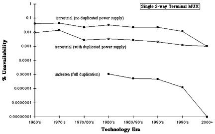
Fig 2. Unavailability of a single 2-way terminal MUX.
Duplicating the power supply reduces the risk to well below that imposed by the station battery and power system for remote locations. Again full duplication of terminal equipment in terrestrial systems is seldom undertaken as the overall system advantage is negligible when compared with the risk posed by the cable and repeaters. Furthermore, it involves the added complexity of hot stand-by switching, sensing and control, which again is not trivial but is less of a problem to deal with than in the repeater case. Full terminal duplication is most commonly adopted on undersea systems since the highest achievable availability is warranted on such critical international routes.
?
3. End-to-end Reliability of Long Line Systems
In order to model circumstances in national and international routes, and-to-end system lengths of 100km, 1000km and 10,000km are assumed. For each system length the model computes the correct number of line repeaters for the technology era. For example, repeater spacings in the copper eras were constrained to 2km, whereas the later optical fibre eras readily accommodate 50km. In the case of a 100km system length, the model therefore invokes 49 repeaters for the copper eras, reducing to 1 for the fibre eras. For 1000km and 10,000km systems these figures scale linearly. This is implicit henceforth.
3.1 Terrestrial Systems
100km terrestrial systems can now be repeaterless but in practice one or two will usually be present as part of flexibility nodes. From Fig 3 it can be seen that the reliability is dominated by the terminal MUX and repeaters throughout the technology eras if power supply duplication is absent. Cable reliability has little influence. However, when power supply duplication is used the reliabilities of all three elements become broadly similar with time. The reducing number of repeaters with time accounts for the observed improvement in their cascaded reliability.
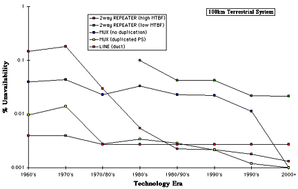
Fig 3. Repeater, MUX and line unavailability for 100km terrestrial systems.
?
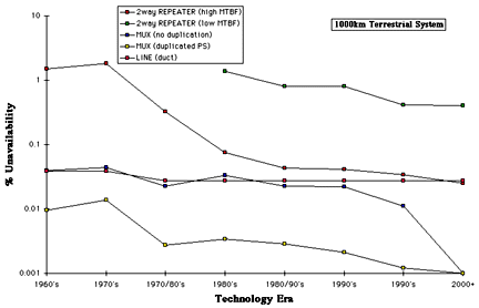
Fig 4. Repeater, MUX and line unavailability for 1000km terrestrial systems.
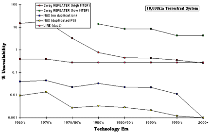
Fig 5. Repeater, MUX and line unavailability for 10,000km terrestrial systems.
Increasing system length to 1000km of course requires more repeaters (19 in the fibre eras increasing to 499 in the copper eras), and this is reflected in Fig 4 where it can be seen that the reliability of the cascaded repeaters now dominates through the technology eras if power supply duplication is absent. Cable and MUX reliability have little influence. However, when power supply duplication is used the repeaters and cable become equally dominant with time. The MUX plays little part in the equation. The reducing number of repeaters with time again accounts for the observed improvement in their cascaded reliability.
As might be predicted, the reliability of 10,000km systems is broadly similar to that observed for the 1000km case because the length dependent elements (i.e., cable and repeaters) dominate the reliability equation. So once again Fig 5 shows that the reliability of the cascaded repeaters dominates throughout the technology eras if power supply duplication is absent, with cable and MUX reliability having little influence. If however power supply duplication is used, the repeaters and cable become equally dominant with time. Duplicating the power supply of the terminal MUX now has such a marginal impact that it is arguably not worthwhile.
3.2 Undersea Systems
Optical fibre undersea systems have been in service since the mid-late 1980's, and this is reflected in the graphs presented in this section.
For 100km undersea systems Fig 6 shows very clearly that cable unavailability always dominates, and this continues to be so for 1000km (Fig 7) and 10,000km (Fig 8) system lengths. This observation is not a reflection on the quality of undersea cables, quite the contrary, it is a direct consequence of the unavoidably high MTTR. Clearly the time taken to dispatch a cable ship plus crew, locate the fault, recover the cable, effect the repair and replace the cable is significantly more than the corresponding time for terrestrial systems (c.f., Table 1). As before, the small observed improvement in cascaded repeater reliability with time for all three system lengths is due to the reducing repeater count.

Fig 6. Repeater, MUX and line unavailability for 100km undersea systems
Fig 7. Repeater, MUX and line unavailability for 1000km undersea systems
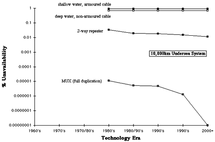
Fig 8. Repeater, MUX and line unavailability for 10,000km undersea systems
It is apparent in the above graphs that the need for MUX duplication recedes with system length, however, there is no compelling argument on the grounds of cost etc for doing away with this duplication and so is generally provided as standard on these important international routes.
3.3 N+1 Stand-by and Diverse Routing
N+1 stand-by is a well established and straight forward practice that improves link reliability by providing one "hot stand-by circuit" for every "N operational circuits". When a failure occurs the affected traffic is automatically switched to the stand-by circuit. The scheme originated out of necessity in the days of twisted pair and coaxial line plant, when repeaters represented the dominant failure mechanism. Its main appeal is the simplicity of the switching equipment involved, whereas the down side is that it provides little or no protection when the cable is the dominant risk, which is nearly always the case. A further limitation of the technique is its limited ability at coping with multiple circuit failures on the same line, due for example to power supply outages, cable breaks, human interdiction, adverse environment, etc. Multiple failures arise through these mechanisms because the stand-by circuits are generally fed from the same power bus, or are in the same cable, or in the same duct. Clearly a better arrangement would be for the stand-by circuits to reside in independent cables that follow different geographical paths between the same two end points. This in fact is the basis of diverse routing (often referred to as network protection) where every effort is made to avoid any form of sharing. The geographic separation between the main and diverse paths can range from a few kilometres within cities to hundreds of kilometres within countries, and ultimately whole countries and continents for international links. Diverse routing is generally limited to long distance, high capacity links because of its high implementation and operating cost.
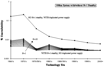
Fig 9. Unavailability of 100km systems with/without N+1 standby

Fig 10. Unavailability of 1000km systems with/without N+1 standby
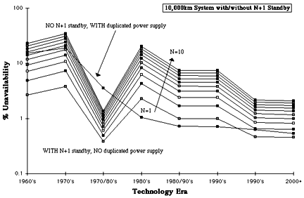
Fig 11. Unavailability of 10,000km systems with/without N+1 standby
Figs 9, 10 and 11 show the impact that N+1 stand-by has on the reliability of 100km, 1000km and 10,000km terrestrial systems. N+1 stand-by may have been right solution in the early days of PCM when other critical factors were at play, but today, and more so in the future, it is clear that this approach wins no meaningful advantage over the significantly simpler use of power supply duplication. At a time when Telco's are striving to increase network utilisation, N+1 stand-by is also now expensive in the broad sense. Realistically a worthwhile advantage can only be achieved by introducing network protection (diverse routing), in which case power supply duplication could also be dispensed with.
3.4 Add-Drops
Long distance terrestrial transmission systems incorporate add-drops at selected points along the cable to extract/insert traffic in support of the network routing/switching functions. For operational convenience these are co-located with repeaters. In our study we assume that each add-drop requires a pair of MUX units back-to-back in the case of PDH, and a single MUX unit for the SDH, with a pair of 2-way repeaters in each case. For WDM operation a pair of MUX units are required but these are passive (i.e., all optical) and hence are highly reliable compared with their electronic counterparts (³ 10x better).
Figs 12. Unavailability of 100km systems with add drops.
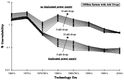
Figs 13. Unavailability of 1000km systems with add drops.
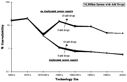
Figs 14. Unavailability of 10,000km systems with add drops.
Figs 12, 13 and 14 show that the impact of add-drops on end-to-end system reliability is a strong inverse function of system length, so much so that their application to 100km systems should ideally be avoided (or used minimally at least). This is because the additional hardware in the add-drops represents a significant proportion of the total system. For the same number of add-drops this proportion of course reduces as system length increases, dwindling to insignificance for 10,000km systems.
?
4. System Reliability in the Local Loop
Telecommunications are at their most vulnerable in the local loop due for example to exposed cables, shallow burial with or without ducts, poles and wire drops. All of these are good targets for other utilities and accidents generally. As a result the risks encountered are orders of magnitude greater per unit length compared with the long lines environment, but fortunately the distances are short and so the risks are manageable.
In our analysis of reliability in the local loop we have adopted the same overall approach used thus far for long distance systems, the primary difference being the significantly shorter line lengths involved and the higher risk of failure or damage to line plant. Not surprisingly we find that the overall balance between the various MTBF's and unavailabilities for the local loop is dramatically shifted.
4.1 Route configurations
The limited transmission and signalling abilities of our copper heritage dictated a local loop with a tree and branch distribution, with switching and flexibility nodes sited at population centres. Fig 15 shows the evolution of node, cable and line plant configurations with time and technology. Although simplistic in content, these configurations are entirely valid for our purposes. For historical completeness and that our study be as broadly applicable as possible, the configurations incorporate a mixture of copper systems (twisted pair and coaxial) and multi-mode and single mode fibre systems, with each configuration pertaining to a particular technology era. Included is the concatenation of different line plants that might arise along a typical route, e.g., duct followed by direct bury then overhead.
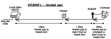
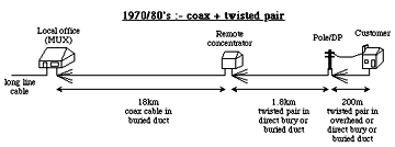


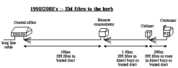


 Fig 15. Local loop configurations through the eras.
Optical fibres raise the possibility of eradicating all of the flexibility points in the local loop, and so remove the risk of failures caused by craft interdiction. Interestingly some ~50% of the faults experienced by telco's today are in the local loop, around half of which are in some way attributable to their own craft people during installation and maintenance. A further ~10% are related to corrosion, with another ~10% to windage, and the rest attributed to other utilities et al inflicting accidental damage.
In our choice of route configurations, particularly those involving fibres, we have purposely discounted contentious issues such as centralised power feeding as this is something of a red herring! Telco's are not power/electricity companies and in the history of telecoms the Central Battery policy is a recent and retrograde solution that jeopardises future developments. All modern telecoms equipment comes complete with a power cord and/or an internal battery. The notion that the advantages of fibre and an all-optical local loop should be jeopardised merely to satisfy yesterdays power feed technology solutions and limitations is a nonsense, and as such is neglected here. The notion of one fibre per customer all the way back to the central office is equally moribund! Sharing the ~5,000GHz bandwidth of a fibre amongst several users by using passive splitters at strategic locations offers a far more economic solution, and so for our future-looking scenarios we assume a Passive Optical Network (PON) configuration.
Clearly the opportunities for reliability improvements in the local loop through the deployment of fibres are significant. The challenge is to realise the obvious benefits whilst consolidating the network into a less hierarchical (i.e., flatter) structure with minimal switching. In short, the future telecoms network becomes a vastly extended local loop. The prize is not just improved reliability and performance, but greatly reduced operating costs, manning levels, improved flexibility and service offerings.
4.2 Reliability
From Fig 16 it is clear that overall unavailability in the local loop has remained relatively constant through the eras. At first sight this would appear inconsistent with the fact that reliability improvements are constantly being realised and deployed. However, it must be remembered that as the new technologies are introduced, bringing the benefit of for example increased capacity and new facilities, they also come with a price - an initial reduction in effective reliability until the new technology matures. The early days of fibres is a classic example of this. The ensemble effect of this is a broadly constant reliability over the eras, but it is important to note that this is in concert with significant increases in capacity, system reach and performance, and equally significant reductions in equipment and operating costs. Some of these trends are illustrated in Fig 17.

Fig 16. Overall unavailability of local lines
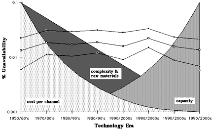
Fig 17. Key trends in relation to unavailability in the local loop
Comparing the overall reliabilities of the local loop and 100km systems (c.f., Fig 9) yields similar figures. The reliability of customer-to-customer links (i.e., local loop + long line + local loop) of this approximate length is therefore evenly distributed between the local loop and long line, which is an optimum situation. However, for links in excess of 100km we find that their reliability is dominated by the long line portion. For example, our results show that a 10,000km long distance route (c.f., Fig 11) has a failure risk >100x that of the local loop. Does this mean we can be complacent in the local loop in the knowledge that for many traffic connections the reliability problems arise elsewhere ? Most definitely NO because it is vital that we view telecommunication as an end-to-end global process. It is desirable on operational and economic grounds to engineer a balance throughout a network with an equitable distribution of failure risk.
?
5. Cable Repair
5.1 All Your Eggs in One Basket
Throughout the history of cable transmission the philosophy has been to avoid putting all your eggs in one basket. That is, to distribute circuits across several pairs, coaxial tubes and fibres. This approach was encouraged by technologies that could support only a limited amount of traffic on individual bearers. With the advent of the optical amplifier this philosophy is about to be changed in a most dramatic way. The ability to place all circuits on one amplified optical fibre using WDM actually improves the overall circuit availability. Let us consider the rationale behind this rather surprising statement. Suppose a cable contains a number of parallel fibres each of which is carrying an equal share of the total traffic in the cable. When the cable is hit, how long does it take to repair ? We might suppose a fixed time to detect, locate, dispatch, and prepare the cable for fibre splicing - say 24 hours (it would probably be considerably less, but we are purposely being pessimistic). Then the repair crew start to splice the individual fibres - say 15-30 minutes per fibre. The MTTR's and unavailabilities that follow from this are listed in Table 5 as a function of the number of fibres in the cable, and these are summarised in Fig 18.
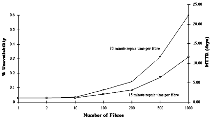
Fig 18. Unavailability and MTTR experienced by the last fibre in a cable failure
For even a modest number of fibres, say 200, the MTTR and unavailability increase rapidly. From the point of view of the last fibre to be repaired, which could be your fibre, this is unacceptable. Now consider that same cable breakage but with all the traffic carried by the previous 200 fibres now on a single fibre using WDM. Now the MTTR and unavailability are only marginally down on the best case figures governed by the static time to detect, locate, dispatch and prepare the cable. To the customer as well as the operator this represents a significantly better availability.
5.2 Detecting and Locating Fibre Breaks
In the case of duplex (bi-directional) and diplex (WDM) transmission over a single fibre, there is an inherent ability to detect the location of a fibre break in real time. It is only necessary to detect an abrupt change in the signal level or error event activity, and then use the phase or path delay as a distance calibration, to be able to accurately position the fault. It is also conceivable that network protection switching could be invoked before the fibre break interrupts service to the customer.
?
6. Further Reliability Considerations in Networks
6.1 Lightning & EMC
Longitudinal currents induced in copper lines by lightning strikes can couple across into the static sensitive electro-optics and MUX equipments in fibre systems causing failures, incipient faults and burst errors. Wherever possible copper and fibre plant should be divorced and steps taken to deflect such induced currents away from fibre plant. A similar situation can also be presented by power grid distribution systems. It should not be assumed that lightening and power transients will not affect fibre systems - they generally do unless some protective action is taken.
6.2 Failure Prediction
Recent studies have shown that it is possible to differentiate between the cause of error bursts on the basis of the error pattern statistics (see the paper by Butler and Cochrane in this issue). Further development of these techniques might enable discrimination between events and alarms to the point where maintenance action can be focused and explanations furnished automatically. Failure type, time and location forecasting is an area now needing attention in order that network reliability and performance be further enhanced.
6.3 Network Management
Monitoring systems and operations, extracting meaningful information and taking appropriate action to maintain a given grade of service is becoming increasingly complex and expensive. The level of complexity increases in proportion (at least) to the amount of data to be handled, much of which is redundant or unusable. For a fully interconnected network of N switching nodes a single fault results in one failure report plus error reports from the N-1 other nodes. We can thus show that:
For example, a network of 500,000 switching nodes each with an MTBF of 10 years will suffer an average of 137 node failures and will generate an average of 68.5 million reports per day. The assumption in the above formula that each node is communicating with all the others is of course somewhat extreme. At the opposite extreme we have the least connected case, which leads to:

which predicts that the reports still count in the millions. Whilst there are certain network configurations and modes of operation that realise fault report rates proportional to N, the nature of telecommunication networks to date tends to dictate a ~N^2 growth. Indeed, a large national network with thousands of switching nodes can generate information at rates of ~2Gbyte/day under normal operating conditions. Maximising the MTBF and minimising N must clearly be key design objectives.
6.4 Software
Today's networks rely heavily on software for its management and service provision operations, while the software itself is becoming more complex involving in some instances millions of lines of code (Fig 19). Coupled with this is the fact that even minor errors in software, either in the base code or in its implementation, pose a considerable risk to network operation, as is evidenced in recent outages which may be quantified using the modified Richter scale in Fig 20.
Fig 19. Foster's Metric - measure of software size/complexity.
?
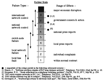
Fig 20. 'Richter' outage disaster scale for networks.
If the present trajectory in software development is maintained, the magnitude of the risk will grow exponentially as we look to the future. In contrast, the reliability of hardware is improving rapidly whilst that of software is reducing, so much so that we are now seeing sub-optimal system and network solutions. From any engineering perspective this growing imbalance needs to be addressed. If it is not we can expect to suffer an increasing number of ever more dramatic failures. A number of technological developments hold promise that this trend can be checked, for example, optical transparency within the network which utilises very simple switching and control methodologies, and distributed intelligence whereby network control becomes less centralised and hence less critical.
?
7. People
The reliability of operational systems is generally less than that predicted at the design stage. Moreover, there are often significant differences between the measured performance of individual units and large numbers co-located in single installations. In most cases this sub-optimal behaviour can be traced back to human intervention causing imperfect repair, interference or incidental damage/weakening. Indeed, evidence suggests that ~50% of the faults experienced by telco's today are in the local loop, around half of which are in some way attributable to their own craft people carrying out their everyday installation and maintenance activities. The figure for long lines, although lower, is nevertheless significant. The replacement of manual distribution points and wiring frames with software based routing on a PON represents a significant gain. When combined with gains arising from the eradication of corrosion, the overall saving can be as high as 40% of the operating total. Similar savings are also possible for repeater stations and switches. A network based solely on fibre with <100 switches would have a fault rate of only ~20% of today's network for fibre to the home (FTTH). If however the fibre only extends to the kerb (FTTK) with copper or radio providing the final drop to the customer, the above suggested gains will not be realised and the overall running costs will remain high. FTTK also introduces a finite bandwidth limitation that prevents future capacity upgrades.
?
8. Quantum Effects & Node Reduction
All of our experience of systems and networks to date, coupled with the general development of photonics and electronics, point towards networks of fewer and fewer nodes, vastly reduced hardware content, with potentially limitless bandwidth through transparency. With networks of thousands of nodes, failures tend to be localised and isolated - barring software related events! The impact of single or multiple failures is then effectively contained by the "law of large numbers", with individual customers experiencing a reasonably uniform grade of service. However, as the number of nodes is reduced the potential for catastrophic failures increases, with the grade of service experienced at the periphery becoming extremely variable. The point at which such effects become apparent depends on the precise network configuration, control and operation, but as a general rule networks with <50 nodes require careful design to avoid quantum effects occurring under certain operational modes. That is, a failure of a node or link today for a given network configuration and traffic pattern may effect only a few customers and go by almost unnoticed. The same failure tomorrow could effect large numbers of customers and be catastrophic purely due to a different configuration and traffic pattern in existence at the time. As we move towards networks with fewer nodes, while at the same time increase the extent of mobile communications at their periphery, we should do so with caution !
?
9. The Total Picture
Our future vision is of a global network in which plant complexity is vastly reduced, transmission and switching is transparent, and all reliability risks are optimally distributed across the planet. To get there we must first overcome certain obstacles. For example, a 100x (or more!) reduction in the number of switches is feasible, leading to a >10,000x reduction in the scale of network management. Routing and control software could undergo even greater reductions with millions of lines of structured code in hierarchical operating systems being replaced by a few hundred lines operating a self organising, intelligent system. The resulting reliability benefits are currently impossible to quantify with precision, but clearly they are significant and will ultimately converge on the fundamental limits to network reliability. This migration would be in concert with the migration of intelligence to the periphery of networks in the form of increasingly sophisticated customer terminals such as computers. Telecommunications is already the nervous system of our planet: the peripheral computing power and mobile users are the neurons! A future based on distributed computing and mobile information intensive services necessitates that a high end-to-end circuit availability be realised everywhere.
In support of this objective, this study has shown that the local loop and long distance systems up to 100km already have the potential of achieving a suitably low unavailability, ~0.01% in each case. On international links however, some form of diverse routing is necessary to achieve a similar figure. In its simplest form this could be achieved by setting up a diverse route to each switch. Such a strategy could improve the ~1% unavailability we computed earlier for a 10,000km link to a level on a par with the local loop, which would represent an optimum balance. In either example, the end-to-end (i.e., local loop + long line + local loop) unavailability would be a very acceptable ~0.03% for any link between any two global locations. Improving this figure would involve considerable expense since it would require total interconnectivity between all switches, the introduction of route diversity into the local loop, and the duplication of all switches, flexibility points, etc.
However, there is more to reliability than simply ensuring that the telecom links needed by customers are available on demand and do not fail during use. Customer terminals are likely to evolve to assume a level of network and interface control that will give rise to complex interactivities that in themselves must be reliable. Multi-media and home-working will add to this. In overall terms it is thus imperative that future networks be configured to employ a minimum of concatenated plant, have direct customer-to-customer capabilities, are lean, clean, inherently reliable and transparent.
The reader might like to contemplate the prospect of networks devoid of any hierarchy (i.e., flat), single switched on a national, international and even global basis, with no more than 2-4 concatenated switching centres on any one communication channel.
?
10. Summary of Key Results
For terrestrial fibre systems the repeater and cable risks are generally dominant, whereas only cable risks dominate in undersea systems.Duplicating power supplies realises the lowest cost solution. towards improving end-to-end reliability.
Human interdiction can dramatically reduce reliability.
Concentrating traffic on a single fibre realises a higher reliability than dispersing across several fibres once optical amplifiers are introduced.
The reliability of the future local loop can be on a par with long lines when diverse routing is introduced.
Minimising the number of switch nodes in the network must be a prime objective.
?
11. Final Remarks & Observations
Without the advent of optical fibre technology it is doubtful if the human race could realise effective global telecommunications. Optical technology is unique in combining an inherent ability for high reliability at very low cost, whilst also providing an almost limitless bandwidth for future exploitation, the lowest power and material usage, the smallest physical size, and a repeater spacing that seemed pure fiction only a decade ago. Looking to the future there is every reason to anticipate that advances in this technology will continue and become even more dominant in all sectors of telecommunications. >From a reliability perspective it is clear that it can deliver more than any other technology. However, we would be well advised to regularly revisit this technology to check the validity of our assumptions and solutions. What was effective and appropriate yesterday may not remain so tomorrow.
In this paper we have examined the reliability of optical transmission systems and networks against a perspective of past, present and future technologies. The challenge ahead is the realisation of transparent optical networks requiring a minimum of software and human interdiction. Such networks will ultimately be required to satisfy the future demands of mobile computing and communication on a global scale. Beyond this we have to look towards new forms of fibre (e.g., that give even lower loss than silica, and/or contain programmable structures to realise integrated signal processing) and networks to create even more reliable solutions.
?
Further Reading
Cochrane, P., Heckingbottom, R. and Heatley, D.J.T., "The hidden benefits of optical transparency", Optical Fibre Communication Conference (OFC'94), USA, February 1994.
Cochrane, P., Heatley, D.J.T., et al., "Optical communications - future prospects", IEE Electronics & Communication Engineering Journal, Vol. 5, No. 4, August 1993, pp. 221-232.
Cochrane, P. and Heatley, D.J.T., "Optical fibre systems and networks in the 21st century", Interlink 2000 Journal, February 1992, pp. 150-154.
Cochrane, P. and Heatley, D.J.T., "Optical fibres - the BT experience", Conference on Fibre-optic Markets, Newport USA, 21-23rd October 1991.
Cochrane, P., Heatley, D.J.T. and Todd, C.J., "Towards the transparent optical network", 6th World Telecommunication Forum, Geneva, 7-15th October 1991.
Heatley, D.J.T. and Cochrane, P., "Future directions in long haul optical fibre transmission systems", 3rd IEE Conference on Telecommunications, Edinburgh, 17-20th March 1991, pp. 157-164.
Hill, A.M., "Network implications of optical amplifiers", Optical Fibre Communication Conference (OFC'92), San Jose USA, 2-7th February 1992, paper WF5, p. 118.
Butler, R.A. and Cochrane, P., "Correlation of interference and bit error activity in a digital transmission system", IEE Electronics Letters, Vol. 26, No. 6, March 1990, p. 363.
?
Author Biographies
Peter Cochrane joined the British Post Office in 1962 and was employed as a linesman and maintenance technician until 1966. He graduated from Trent Polytechnic with a BSc Hons in Electrical Engineering in 1973 and gained an MSc, PhD and DSc in telecommunications systems from the University of Essex in 1976, 1979 and 1993 respectively. He is a fellow of both the IEE and IEEE, a visiting professor to Essex and Southampton Universities, an honorary professor at the University of Kent, and a visiting fellow to University College, North Wales at Bangor. He joined BT Laboratories in 1973 and has worked on a variety of analogue and digital switching and transmission studies. He has been a consultant to numerous international companies on projects concerned with systems, networks and test equipment development. In 1978 he became manager of the Long Lines Division where he was involved with the development of intensity modulated and coherent optical systems, photonic amplifiers and wavelength routed networks for terrestrial and undersea applications. He received the Queen's Awarded for Technology in 1990 as manager for the production of optical receivers for TAT-8 and the PTAT-1 undersea cable systems. In 1991 he was appointed to head the Systems Research Division at BTL which is concerned with future advanced media, computing and communications developments. During 1993 he was promoted to head the Research department at BT laboratories with 620 staff dedicated to the study of future technologies, systems, networks and services. He is also the Development & Procurement board member for technology.
David Heatley joined the British Post Office in 1971 as an apprentice telecommunication engineer. In 1974 he won a scholarship to study Electronic Engineering at Heriot-Watt University, Edinburgh. After graduating in 1978 with 1st class honours he joined BT Laboratories to take up a research position working on the development of early optical fibre systems. As the recipient of the Flowers Scholarship in 1980, he continued his university studies and in 1981 gained his MSc in Telecommunications Systems from the University of Essex. Upon returning to BT Laboratories, he worked on the development of analogue optical fibre video systems which utilised a variety of intensity modulation and coherent techniques. Through this work he gained his PhD in Optical Communication Systems from the University of Essex in 1989. In 1985 he was appointed to head a group responsible for the development of optical receivers for terrestrial and undersea applications. In particular he was responsible for the design and final performance testing of receivers specifically developed for the TAT-8 and PTAT-1 undersea cable systems, two of the world's first transatlantic optical systems. In this capacity he was a member of the team that received the Queen's Award for Technology in 1990. Since 1991 he has been heading a team looking at future network technologies and services. He is a Member of the IEE and is a Chartered Engineer.