Preprints & Reprints
Back to Preprints & Reprints > Publications & Opinion > Homepage
Optical Telecommunications - Future Prospects
Peter Cochrane David J T Heatley Peter P Smyth Ian D Pearson
Abstract
Optical technology is already the dominant carrier of global information. It is also central to the realisation of future networks which have the capabilities demanded by society. For example, essentially unlimited bandwidth to convey services of any kind, full transparency that allows terminal-only upgrades in capacity, and flexible routing of channels, are some of the key features that cannot be provided by alternative technologies. In the main, all of the necessary elements for such networks already exist in experimental form, and rapid progress is being made towards a field deployment capability. This will bring about a paradigm change in the whole nature of telecommunications as we move into the third millennium.
Historical Perspective
During the hundred years or so since telecommunications first became established, advances in the technology and services offered have been astounding, particularly within the last decade through the deployment of optical fibres. Indeed, some 60% of the world's telecommunication traffic is now carried over optical fibres, and is expected to reach 85% by the turn of the century (Fig 1) . In the UK the figure is already at 80% and promises to exceed 95% by the turn of the century. A number of key issues have brought this about.
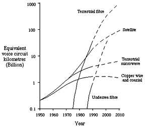
Fig 1. Global transmission capacities
Firstly, the transmission capacity of individual cable routes, and the traffic handling capacity of the network as a whole, has increased significantly through the deployment of optical fibres (Fig 2): the typical bandwidth of a fibre is potentially ~40,000GHz, with ~6,000GHz available today, which compares favourably with <1GHz for a good coaxial cable and <300GHz for microwave radio. Although barely 1% of the bandwidth of fibre can be accessed with present day technology, this is expected to approach 100% within 15-20 years (Fig 3). The intrinsically small size of optical cables has been a crucial enabler in their deployment, not forgetting that prior to this underground ducts were rapidly becoming congested with metallic cables and that telecommunications operators were thus facing severe constraints on expansion.
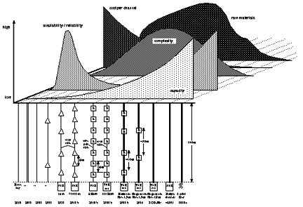
Fig 2. History and trends in telecommunications
Secondly, the take-up of optical fibres has reduced the per channel installation and running costs, partly due to the greater available capacity, but also through the reduced complexity of the transmission paths and the correspondingly higher reliability and availability (Figs 4-6). The reduction in complexity has occurred in phases, commencing with the move from multimode to single-mode fibre, at which point repeater spacings increased from a few km's up to 30km. This was followed by the opening of the 1550nm window, which increased repeater spacings to 100km through the lower fibre loss. Indeed, many fibre routes are now repeaterless, and those longer routes which still require repeaters are migrating towards using optical amplifiers, thereby significantly reducing the component count. The number of switching centres is also expected to reduce with the phased introduction of all-optical routing. With this overall reduction in component count will come a corresponding increase in reliability.

Fig 3. Utilisation of fibre bandwidth with time
Thirdly, the raw material usage in optical fibres is a small fraction of the corresponding usage for metallic cables (Fig 7). Coupled with this is the fact that silica, the primary constituent of optical fibres, is the most abundant element on the planet and is readily harvested, whereas natural copper resources are in danger of exhaustion and require complex and expensive mining. Moreover, the processing of raw silica into telecommunication grade optical fibre expends significantly less energy and expels fewer (if any) pollutants than the smelting and refining processes necessary for copper.
Given that the take-up of optical fibres within telecommunications is already substantial and that an exponential increase with time is anticipated into the next century, what can we expect in the future? This paper outlines those areas of telecommunications that are likely (even certain) to benefit most dramatically from ongoing and future advances in optical technology, paying particular attention to those that follow directly from real achievements evident today. The overall objective of this paper is to present the case that the future of telecommunications is secure with the exploitation of latent optical technology to the fullest extent.
The Optical Amplifier
Arguably the most significant modern day development in the field of optical telecommunications, and the one which promises to have the greatest impact on the future, is the optical amplifier. When used as in-line cable repeaters, not only do they reduce the component count in the transmission path, which has clear benefits to reliability and running costs, but they also open up the full bandwidth of the fibre windows (~6,000GHz with today's technology) between switching centres. They also allow the development of novel transmission and network concepts that take full advantage of the linear and non-linear properties of the fibre.
The first optical amplifiers successfully developed were based on semiconductor lasers . Their Fabry-Perot structure gives rise to certain fundamental features which limit their overall performance and have detracted from their widespread use. Most critically they are polarisation sensitive, temperature dependent, they suffer at least a 3dB coupling loss at each facet which in turn reduces gain and means that noise figures are typically 8-10dB (6dB best case), and their gain and wavelength profiles are largely determined by the geometry and optical characteristics of the resonant cavity, both of which are difficult to control during fabrication. Nevertheless, through their small size and GaAs material base they are now receiving attention with regards to their integration with other GaAs devices and waveguides to form opto-electronic IC's (OEIC) for switching centres, for example: zero loss switches , splitters and WDM multiplexers ; edge-coupled broadband PIN photodiodes with gain ; photonic processing.

Fig 4. Schematic diagram of fibre amplifiers and gain -v- wavelength profiles
The majority of today's developmental work is devoted to Erbium doped fibre amplifiers (EDFA) since they can readily realise the features crucial to high performance transmission systems . They are fundamentally linear, insensitive to polarisation and offer high gains with efficient optical coupling over a 40nm bandwidth (~5,000GHz). Furthermore, their principal parameters are defined by atomic composition rather than physical geometry, which means that consistency (and hence yield) during manufacture is high. Their realisation is simple through the direct doping of a silica fibre core to provide a medium which affords gain when optically pumped at an appropriate wavelength, presently 980nm or 1480nm because of the availability of semiconductors lasers which couple sufficient power at these wavelengths (Fig 8). The length of doped fibre can range from 1m to tens of kilometres, with state-of-the-art gains exceeding 40dB and output powers in excess of +20dBm. Packaged production EDFA's with integral control electronics and pump lasers are now closely approaching these performance figures. Examples of these for CATV, undersea and terrestrial long lines applications are shown in Fig 9. The transmission distances that have been achieved to date over experimental multi-amplifier routes are summarised in Fig 10.
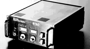
Fig 5a. Commercial Erbium-doped fibre amplifier for developmental work

Fig 5b. Commercial Erbium-doped fibre amplifier for terrestrial systems
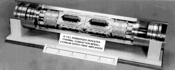
Fig 5c. Commercial Erbium-doped fibre amplifier for undersea systems
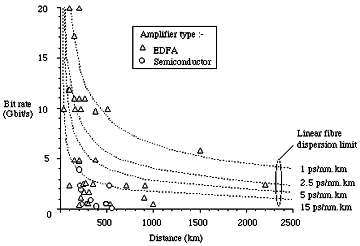
Fig 6. Reported multi-amplifier experiments and field trials
EDFA's are capable of realising a noise figure close to the 3dB theoretical minimum, particularly when pumped at 980nm. This renders them attractive as receiver pre-amplifiers to improve sensitivity. In this application the receiver as a whole comprises a low noise figure EDFA followed by a narrowband optical filter (typically 1nm or less) to minimise spontaneous noise products reaching the photodiode, and then a low noise, broadband PIN receiver. Fig 11 summarises the best sensitivities reported in the literature, from which it is clear that substantial sensitivity improvements (³20dB) can be achieved over un-amplified receivers. It should be noted that the sensitivity of pre-amplified receivers exceeds that of coherent systems at high bit rates: this represents a major cost advantage in favour of the pre-amplified approach since it embodies a simple direct detection design. In addition, the tunability of coherent receivers can now be approached by pre-amplified receivers with a suitably chosen interstitial filter.
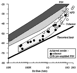
Fig 7. Best reported receiver sensitivities
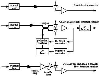
Fig 8. Principal receiver configurations
Most recently, optical amplification via Erbium doping has been demonstrated with a Silica waveguide, rather than a fibre. Such amplifiers open the way to the realisation of compact lossless networking elements of the kind briefly alluded to above in relation to semiconductor laser amplifiers, but in waveguide rather than fibre form and affording many of the intrinsic advantages of Erbium derived amplification.
A further class of fibre amplifier that is receiving attention for certain applications exploits the non-linear properties of the Raman scattering mechanism to generate gain. Gains in excess of 40dB and output powers exceeding +30dBm are achievable, however, very high pump powers are required and noise and intermodulation levels can be high. A comparison of typical pump power and gain characteristics achievable today is given in Fig 12. As this data relates to work in the past 3 years, significant improvements in the next decade can be reliably anticipated.
It is important to recognise that transmission practice thus far has conditioned us to viewing in-line amplifiers/repeaters as discrete entities: the "black box" syndrome. With the advent of fibre amplifiers (Erbium and Raman) has come the prospect of distributed amplification, where the line fibre itself provides gain. Under these circumstances transmission is truly lossless. Furthermore, theory predicts that distributed amplification is optimal regarding noise accumulation: an echo of our earlier analogue FDM heritage! Experiments have successfully demonstrated lossless transmission over distances of 50km, and the prospects for significantly longer distances are good.
Clearly fibre amplifiers, particularly the Erbium doped variety, in either discrete or distributed form, will be central to future networks. Their initial deployment will be as linear in-line amplifiers on cable routes, beginning with selected terrestrial routes and then rapidly broadening to include transoceanic undersea routes. For example, the TAT-12 and TAT-13 transatlantic systems, scheduled for service in 1995 and 1996 respectively, will each utilise discrete EDFA's throughout their ~6,500km length. They will provide 5Gbit/s capacity per fibre between the UK and the USA, and France and the USA respectively: at least 10 times the capacity per fibre of today's transatlantic systems.
Soliton Systems
The transmission distances alluded to earlier in Fig 10 relate to the fibre behaving as a linear transmission medium. However, fibre is fundamentally non-linear, primarily manifested as dispersion. In order to transmit over distances beyond the dispersion limit, for example on transatlantic cable systems, electro-optic regeneration has been necessary at regular, relatively short intervals on route. Optical amplifiers can be introduced to replace certain of the regenerators but the resulting accumulation of dispersion and noise dictate that electro-optic regeneration must still be performed after ~3-10 amplifiers, depending on a variety of system and fibre parameters.
A new generation of transmission systems exploit rather than fight against the non-linear properties of fibre, and in so doing achieve all-optical transmission over several thousand kilometres. The key to these systems is the Soliton: a particular pulse shape which, when correctly launched into the fibre, maintains its shape as it propagates down the fibre: linear distortion (pulse spreading through dispersion) exactly cancelling non-linear portion (pulse narrowing through the Kerr effect). After a certain distance along the fibre (the Soliton Distance), solitons do eventually succumb to attenuation and dispersion and break down. However, by placing optical amplifiers at critical intervals along the cable significantly shorter than the soliton distance, or better still by using distributed fibre amplification, pulse breakdown is avoided.
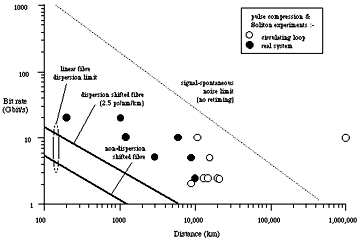
Fig 9. Transmission distances using solitons
A number of experimental soliton systems have been reported in the literature, some using circulating fibre loops to simulate long cable lengths (e.g, ³6,000km), while others use real fibre over more modest distances (e.g, ~1,000km) to model more closely the true behaviour of a system. Fig 13 summarises the key bit rate/distance achievements in laboratory trials to date. It is clear that all-optical transmission at Gbit/s rates over transatlantic and transpacific distances are feasible. Indeed, at the time of writing this paper, the authors were aware of work about to be published in the open literature in which 2.5Gbit/s soliton transmission is successfully achieved over 10,000km of concatenated fibre. There is however a real price to pay in that the section length between amplifiers in a soliton system may be typically half that of a conventional linear system, which clearly raises cost and complexity. Trade-offs will undoubtably exist between the linear and soliton options, the optimum choice being in some way application dependent. For example, the possibility of applying WDM to solitons may well compensate, to some extent, for the number of additional amplifiers required. However, experiments have shown that long distance systems (e.g, transoceanic) may be limited to 2-3 wavelengths due to various interaction mechanisms intrinsic to solitons, while shorter systems, although subject to the same interactions, may support additional wavelengths.
Transparent Optical Networking - The Optical Ether
In those networks (e.g, the UK network) where dual window fibre has been deployed, EDFA's could be readily applied to existing 1.3um regenerated routes by adopting the piggy-back arrangement in Fig 14. Low loss WDM couplers ensure that the existing 1.3um path is unchanged (bar a small increase in loss), while the EDFA's open up the 40nm bandwidth (6,000GHz) of the 1.5um window of the same fibre. Experiments have proven the feasibility of this approach. Since the 1.5um channel is effectively transparent, later upgrades in transmission capacity and/or mutiplexing to accommodate a mixture a signal formats (digital, analogue) need only involve modifications of the terminal equipment. Upgrades to the 1.3um channel would require all regenerators to be modified in addition, and the extent of the upgrade would be severely constrained by the limitations of the electronics.
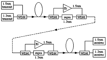
Fig 10. 1.5um optical amplification over existing 1.3um electro-optic route
Whilst the gain characteristics of silica based EDFA's are centred on the 1.5um window (Fig 8), recent work with fluoride host fibres has demonstrated amplification in the 1.3um window which is uniquely attractive due to its zero dispersion. Given such devices to replace the 1.3um regenerator in Fig 14, optical amplification would then be achieved in both fibre windows, with the attendant benefits of upgradability available to each. Clearly the ultimate engineering solution would be to replace these two amplifiers (one per window) with a single amplifier. The technology that would achieve this in a doped-fibre form is presently unclear, whereas certain semiconductor devices show promise.
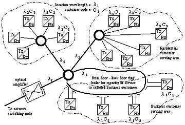
Fig 11. The optical ether concept
Having removed the need for electronic constrictions in the transmission path, the question arises as to how we can exploit this new degree of freedom. If we now start to view the bandwidth of fibre in the same way that we consider radio, we rapidly migrate towards an Optical Ether. Moreover, this is a natural extension of the present Passive Optical Networks (PON) being developed for the Local Loop and LAN applications. The basic configuration of such an ether is shown in Fig 15. To address an endpoint terminal all that is required is the area wavelength (not area code) and the final (fine grain) wavelength for WDMA, frequency for FDMA or code in the case of CDMA. Related studies have shown that this approach could be extended to the replacement of the central office for up to 200,000 lines with a 100% non blocking capability, with potential for improvement to 4-million lines. At todays service levels with a similar level of call/service blocking, up to 20-million lines could then be accommodated, with a potential for significantly more. Beyond this level the need for conventional switching of some kind becomes necessary again. Fig 16 gives a schematic of a system that has been used to dimension the problem and provide a focus for study. The key assumption is that all the optics and control for steering and selecting wavelengths resides in the customer terminal.
The ether concept as described has been demonstrated in the laboratory with a small number of terminals switching 100Gbit/s capacities, and in the London fibre network with more modest capacity levels. The key problems and limitations now hinge on the realisation of sufficiently miniature and reliable electro-optics, memory capacity, control systems and wavelength standards. The rate of developmental progress towards all of these requirements currently puts commercial realisation in the 2010 time frame. However, on the way, the trajectory of development is likely to see many variants of the same basic concepts. It is perhaps most likely that the first area of exploitation will be for LAN's of modest numbers of terminals where the allocation of an operating wavelength and transparent channel will remove the need for over complex and bandwidth constraining TDMA/ATM schemes. This will become both inevitable and a necessity as computer clock rates exceed 1GHz and electronic limitations start to impinge above 10GHz.
Another interesting prospect for transparent networks is that of customer mobility. It is possible to transport raw microwave signals over fibre with only a single stage of frequency translation at each end. A radio cell can therefore be replicated over several remote and diverse locations to give the illusion of a single location. Effectively six company locations start to appear as one to the individual user. The obviousness of this prospect increases with the realisation that optical wireless is also being developed for in-building and street use for both telephony and broadband services.
Optical Wireless
An exciting prospect for offices and commercial buildings of the 1990's is the deployment of ubiquitous Wireless Local Area Networks (WLAN) which offer portability and networking of Laptop and Pen computers. Such networked computers could offer telecommunications services such as video phones and electronic messaging and provide access to multi-media applications. Wireless communication commonly uses radio or microwave techniques, however the radio spectrum is a scarce resource and the pressure to be economic with its use is ever increasing. Allocated channels are therefore usually narrowband (typically 20 MHz) which means that broadband wireless transmission for densely populated buildings is not possible. Optical wireless systems [37,38] on the other hand afford the required mobility within buildings, are intrinsically broadband, and by operating in the infra-red (850 nm) allow low cost LED/lasers and silicon photodiodes to be used. In addition, since the radiated signals are completely contained within the room in which the system is operating, security is intrinsically better than either radio or microwave wireless systems.
Optical wireless transmission can take two forms. The first uses a direct line-of-sight (LOS) link between the transmitter and receiver, while the second uses a diffused link in which the light is reflected off various surfaces (e.g, walls, ceiling) and hence arrives at the receiver via different paths. Each system has its own merits which favour particular applications and environments. For example, the LOS system readily supports high capacity transmission at potentially Gbit/s rates, limited in principle only by the electronics, whereas the diffused system is constrained by multi-path dispersion to more moderate capacities of typically 100Mbit/s. However, the LOS system requires access to at least two different paths to ensure link availability in the event of one path being blocked, whereas the diffused system is largely unaffected under such conditions.
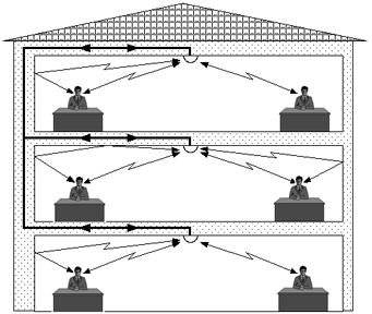
Fig 12. Deployment strategy for diffuse optical wireless in an office
A typical deployment strategy for diffuse optical wireless in an office is shown in Fig 12. The satellite on the ceiling illuminates the walls and floor of a room creating a diffused optical field. It also receives signals from terminals located within the room. The ceiling satellites could be interconnected via a conventional metal cable network, or via an optical fibre network. To avoid interaction between the various users, such systems would utilise multiple subcarriers of differing frequencies, with one pair (i.e., send and receive channels) being assigned to each user. The number of subcarriers that can be simultaneously supported by the system establishes an upper limit to the number of users in one room. The same subcarrier frequencies can of course be re-used in different rooms.
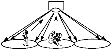
Fig 13. Cell defining through the use of holograms
In order to realise subcarrier re-use within a single room, use can be made of computer generated holograms [39] in the ceiling satellite to direct the light into discrete cells (Fig 13). Due to the very short wavelength of the infra-red light used in such systems (e.g., 850nm), the boundaries of these cells can be very sharply defined both in location and shape, and their size can be dimensioned to illuminate several users or a single individual at his desk. Through subcarrier re-use in adjacent cells, the number of users that can be supported in a single room is significantly increased.
Such holograms are also advantageous with regards to the optical power densities that can be safely tolerated by the human eye [40]. Since they effectively destroy the phase coherence in the wavefront of the light radiating from the ceiling satellite, it is impossible even when directly looking at the satellite for the light to focus down to a spot at the retina. This means that higher power densities can be used than would otherwise be possible, with an accompanying improvement in the transmission performance of the individual links and the ability to transmit at higher speeds. This becomes even more pronounced with operation in the far infra-red (e.g., 1550nm) since the safety limits being proposed are some 10 times higher than those for the more commonly used 850nm wavelength. This is a direct consequence of the substantially reduced sensitivity of the eye to the longer wavelength.
The range of in-building distribution applications to which optical wireless can be put is sure to lead to a diversity of physical layouts and infrastructures. These may well include corridors, multiple connected rooms, galleries, open plan offices, etc. In many of these environments it would be an advantage to use the optical equivalent of a leaky feeder as the transmitter. This can be realised by coupling light from the core of a long run of D-fibre, either selectively at "taps" or distributively. This affords intrinsically accurate control over the power density and distribution of the radiated optical signal. A single continuous length of such a fibre would be laid along a wall, ceiling, staircase, etc, running the length of the area to be covered. Information could then be conveyed to multiple users located throughout a building in a way that is simple to install and distributes power in a safe and uniform manner.
New Equipment practice - The Optical Bus
The concept of distributed amplification with Erbium doping can be applied to data buses. For example, the optical equivalent of a ?tapped bus? has been demonstrated using D-fibre couplers in a bus network of weakly amplifying fibre (Fig 18). Although noise accumulation will eventually dominate, it is nevertheless feasible that such buses could grow to accommodate >1000 taps. This, coupled with recent demonstrations of fibre amplifiers used to offset splitter loss in an optical branching network with a fan-out to several million customers (Fig 19) opens up the concept of the Virtually LOssless Network (VLON).
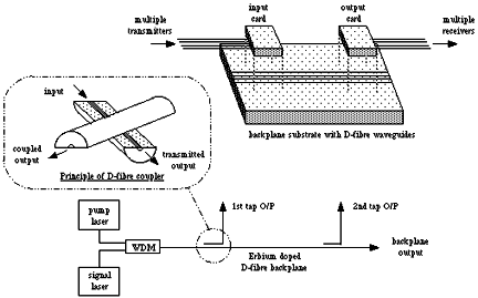
Fig 14. Amplified optical backplane/bus using Erbium doped D-fibres
The implications of the VLON concept on the design of small or large network architectures has yet to be explored but certain opportunities are already clear. Consider for example the possibilities of network configurations using distributed and lumped amplification, transparent in both the 1.3um and 1.5um windows, with a distance elasticity that reaches between cities, and wavelength selective taps or broadband fan-outs that reach all switches. Such configurations are multi-dimensional in that space, time and wavelength/frequency may be simultaneously accessed and traded. When the VLON concept is configured as a switching node the multi-dimensionality allows bandwidth to be traded with hardware simplicity, as has recently been demonstrated in the powerful MONET (Multi-dimensional Optical NETwork) switch/interconnect concept (Fig 20).
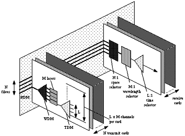
Fig 15. The MONET principle for L x M x N channels
Traditionally switches have only utilised two parameters to route traffic or access data: space and time. MONET utilises a third and highly valuable parameter: wavelength. Using this additional parameter is at present the only way the bits/unit volume at switching centres can be increased without exceeding the energy/unit volume of existing building stock into the new millennium (Fig 21).
Analogue -v- Digital Transmission
The history of telecommunications has undergone cyclic changes with regards to the use of analogue and digital transmission (Fig 22). The earliest form of digital transmission: telegraphy using Morse Code, was replaced by analogue transmission over a century ago with the arrival of the telephone. Analogue remained dominant in a Frequency Division Multiplex (FDM) form up until the late 1950's at which point digital Pulse Code Modulation (PCM) was introduced. Within three decades the balance had inverted, with digital Time Division Multiplexing (TDM) substantially dominating over analogue. Today there is a hint of a further change, perhaps not a complete inversion, but more a converging of the TDM and FDM schemes. This follows from the extensive interest in the use of subcarrier modulation (SCM) to assemble large multiplexes of channels. SCM uses analogue modulation to place individual or blocks of signal channels (analogue or digital or a mixture of both) on to high frequency sinusoidal subcarriers. When combined with WDM it affords a convenient way of increasing the utilisation of fibre (Fig 3) without recourse to high speed electronics and elaborate synchronisation. It achieves this through the simplicity and flexibility of its analogue basis.
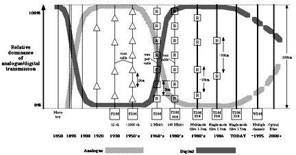
Fig 16. Cyclic trend in Analogue -v- Digital transmission
A further line of reasoning for the future convergence suggested in Fig 22 comes from the present migration towards intelligent networking, neural networks, intuitive network management, and a more heuristic mode of problem solving and operation. Consider how the human brain functions and what constitutes intelligence. Thoughts, emotions and the capacity to learn are not only governed by the presence or absence of a chemical and electrical stimulus at synaptic nerve sites, they are also the result of a highly complex interaction through a network of dendrites linking numerous chemicals and stimuli at these sites, i.e, they are analogue. It therefore seems plausible that an intelligent network in the strict sense can only be truly intelligent if it utilises analogue (i.e, intuitive rather then wholly logical) methodologies. This does not mean that transmission within such a network must be all-analogue, quite the contrary since digital will always afford certain important performance advantages during transmission. It means more that the way in which the network manages data, routes traffic, and affords global control and supervision would be analogue in nature, or at least partially so.
Optical Processing and Computing
The use of optical technology in storage and signal processing is becoming common place in certain application areas: witness optical hard disks for personal computers and domestic CD players. The impact of optical processing on telecommunications has yet to be experienced but is likely in time to be as profound. For example, optical processing will provide a major input to neural network development. Indeed, many research-level neural networks are being realised in optical components. The main reason for this is the ability of optics to offer massive parallelism and interconnections. Since these parameters are fundamental to the principles of neural computing, optics is clearly suitable, so much so that the technologies are likely to develop very closely. Fig 23 shows how an optical neuron would compare with the biological original.
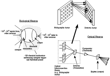
Fig 17. Biological and optical neurons
There are many incentives to migrate towards optical processing (Fig 24). The principal advantage is the potential for high speed, although the physical elegance is also appealing. Speed comes from many factors. For example, optical computing has a variety of ultra-fast physical effects on which to base logic devices. Speeds of picoseconds and below are possible, although further development is needed before this potential is achieved in practical implementations. Another advantage is the low energy required by the relevant optical devices. One of the key devices, a Self Electro-optical Effect Device (SEED) requires switching energies down in the femtojoules per square micrometer regime. If devices can be made small enough to achieve large scale integration, the low energy feature will be a major benefit. Optical computing also demonstrates much greater potential for parallelism than electronics. Fig 25 shows how a massive 10 12 parallelism may be realised in an optical processor, using a holographic element, a 1 million element lens array, Spatial Light Modulator (SLM) and a million element detector array. The nature of this device is analogue by virtue of its linearity and massive parallelism. By combining such parallelism with the developing ability to construct holograms by computer in real time, the true potential of optical computing then becomes visible.
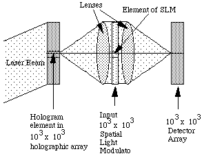
Fig 18. Optical processor
Optical computing is likely to have a broad impact on telecommunications. In an optical transmission network, it would allow information to be read, processed and stored entirely in the optical domain, offering significant improvements in speed and capacity for packet networks. Nevertheless, it is unlikely that optical computing will replace the present electronic methods, indeed the two methods are complementary. For example, optical devices are currently rather slow, the potential in optics coming mainly from the degree of parallelism that can be achieved. Furthermore, the precision of optical devices in presently inadequate for computing on a worth while scale. Whether these factors will remain true as the technology develops remains to be seen.
For those wishing to employ a photonic emulation of electronic - i.e, the optical AND, NAND, OR, NOR and EXOR functions - it is worth noting that it is difficult to create these and achieve a physical dimension <30 l. So the notion of directly replacing the personal computer or mainframe on a digital one-to-one basis may lead to a machine 30-40 times larger. With a 1um feature size, an electronic AND gate is currently <10um across, whereas its optical equivalent at a 1um wavelength would require >30um of space, and more likely >100um in practice. The future of the optical approach is more likely to be constrained to high speed "front end" processing rather than for core functions. Current examples include high speed A/D conversion and sampling functions for radar and instrumentation processors. It is difficult to see how optics will compete in the core processing areas of digital computers and processors. However, in an analogue realisation, the converse is true. For example, performing a Fourier Transform optically using a hologram or grating is near instantaneous and requires minimal software compared with the digital approach.
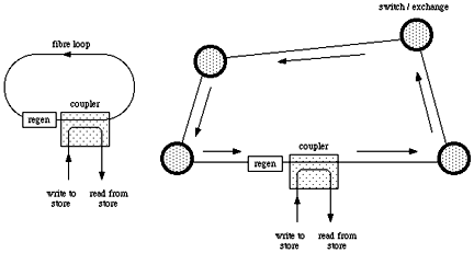
Fig 19. Optical storage using a discrete fibre loop (left) and looped fibre paths in the network (right)
An entirely different approach to optical storage might use the fibre network itself. A fibre can be configured as a volatile data store by creating a circulating loop (Fig 26). By including regeneration in the loop, injected data will circulate perpetually, and can be read-off or over-written at any time. The loop itself can either be a permanent installation in the network which is accessed as required, or a dynamic entity which is established via switching centres only when the need arises. For example, ~2.5Mbits of data could be stored on a compact 50km drum of fibre (typically 25cm diameter, 25cm long) by injecting/circulating the data at a modest 10Gbit/s. On a larger scale, by setting up a loop between London and Birmingham (~400km total path length) and injecting/circulating data at 40Gbit/s, 80Mbits of data can be stored. These capacities can be readily increased by introducing WDM so that the loop supports a number of independently circulating data streams on separate optical carriers. The factor by which the capacity is increased equals the number of wavelengths.
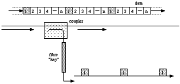
Fig 20. Coding a fibre by writing a structure in the core
Fibres can in themselves afford a degree of storage and optical processing by virtue of "structures" than can be written into their cores. These structures comprise variations in the refractive index of the core, the periodicity of which give the fibre particular properties. For example, a grating structure gives the fibre a wavelength dependent attenuation which, in its simplest form can realise an optical filter, or in a more complex form an equaliser to flatten the frequency response of an optical amplifier. In either case, the fibre is processing the optical information by presenting low loss transmission to some wavelengths and high loss to others. Other processing functions than can be readily envisaged including wavelength dependent splitters and combiners, MUX and DEMUX elements, and so on. By extending this technology it may be possible to write a structure in a fibre core which carries a code that is unique to an individual, akin to the personal identity number (PIN) used on charge cards, etc. This fibre would be that individual's "key" to the fibre network: by inserting his key he can access the network but only data which is headed by his PIN is accepted by his fibre, access to all other data is denied (Fig 27).
Closing Remarks
The imminent development of many novel aspects of optical technology (e.g, fibre amplifiers, soliton systems) to a commercially realisable form will change the course of telecommunications as we approach the next century, stimulating radical and fundamental changes in systems and networks. The release of the full fibre bandwidth will bring about the realisation of the transmission engineer?s dream:
- Near infinite bandwidth
- Near zero path loss
- Near zero path distortion
- Near zero material usage
- Near zero power consumption
- Near zero cost
Probably the most radical commercial changes in the 21st century resulting from the further advance of optical technology will be associated with: the introduction of new services; the realisation that distance and bandwidth will be irrelevant - service and time will become the measures for charging; services migrating to the periphery of networks; local calls extending across complete countries and perhaps spanning all of Europe, and ultimately the globe.
Perhaps the most exciting feature of this prospect is that the fibre required is largely in place already !
Author Biographies
Peter Cochrane graduated from Trent Polytechnic with a BSc Hons in Electrical Engineering in 1973 and gained an MSc and PhD in Telecommunications Systems from the University of Essex in 1976 and 1979 respectively. He is a Fellow of both the IEEE and the IEE and is currently a visiting Professor to Essex University and the Polytechnic of East London, and a visiting Fellow to University College, North Wales at Bangor. He joined BT Laboratories in 1973 and has worked on a variety of analogue and digital transmission studies. In 1978 he became manager of the Long Lines Division where he was involved with the development of intensity modulated and coherent optical systems, photonic amplifiers and wavelength routed networks for terrestrial and undersea cable applications. He received the Queen?s Award for Technology in 1990 for his role as project manager in the production of optical receivers at BTL for the TAT-8 and PTAT-1 undersea optical cable systems. In 1991 he was appointed to head the Systems Research Division which is concerned with advanced computing and communications in the 10-15+ year time frame.
David Heatley joined BT Laboratories in 1978 upon graduating from Heriot-Watt University, Edinburgh, with 1st class honours in Electronic Engineering. As the recipient of the Flowers Scholarship in 1980, he continued his university studies and in 1981 gained his MSc in Telecommunications Systems from the University of Essex. Upon returning to BT Laboratories, he worked on the development of analogue optical fibre video systems which utilised advanced intensity modulation and coherent techniques. Through this work he gained his PhD in Optical Communication Systems from the University of Essex in 1989. In 1985 he became head of a group responsible for the development of advanced optical receivers for terrestrial and undersea applications. In this capacity he was a member of the team that received the Queen?s Award for Technology in 1990. He is now an Engineering Advisor in the Systems Research Division, with special responsibility for future studies and telemedicine. He is a Member of the IEE and a Chartered Engineer.
Peter Smyth joined the Post Office in 1972 as a technician and was sponsored in 1976 as a engineering student at The City University, London. He graduated in 1980 with a 1st class honours degree in Electrical and Electronic Engineering. Since 1980, he has worked at BT Laboratories, first as a research engineer involved in the design of high speed fibre optic systems. He was responsible for developing PINFET receivers which later included GaAs ICs. He has written over 20 papers on fibre optic systems and receiver design. In 1986 he graduated from University College London with a masters degree in Microwave and Modern Optics. In 1988 he was appointed as an Engineering Advisor specializing in new optical concepts for communication systems. In 1990, he was appointed as a group leader in the Technology Research Division where his group worked on new technologies and system concepts. This included Erbium fibre amplifiers, superconductivity, SiGe HBTs and more recently optical wireless.
Ian Pearson graduated in 1981 from Queens University, Belfast with a BSc Joint Honours in Applied Mathematics and Theoretical Physics. After four years at Shorts working on missile design, he joined the Performance Engineering division at BT Laboratories in 1985, specialising in analysis of computing and related networks and protocols. After three years he moved to the Local Access division where he studied ATM transmission over optical networks, and invented the Addressed Time Slice transmission system, ATS. In 1990, he moved to the Network Studies Unit, where he worked on broadband networks and services, and advised on the impact of new technologies on telecommunications. Among his inventions here were an Active Contact Lens and other computer interfaces. Since 1991 he has worked in the Systems Research Division, looking at advanced networks and services.